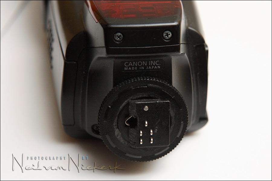
Repairing the Canon 580EX hotshoe foot
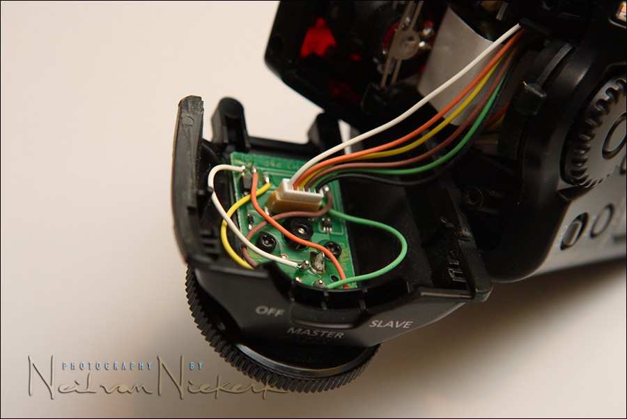
Since the 580EX has a plastic foot, it is very easy to snap it off in the camera’s hotshoe. The photo above shows the typical damage sustained.
The repair is simple, and the cost of the part from Canon’s Service Center.
The part nr is: CY2-1227-000
Replacing the broken foot is relatively easy:
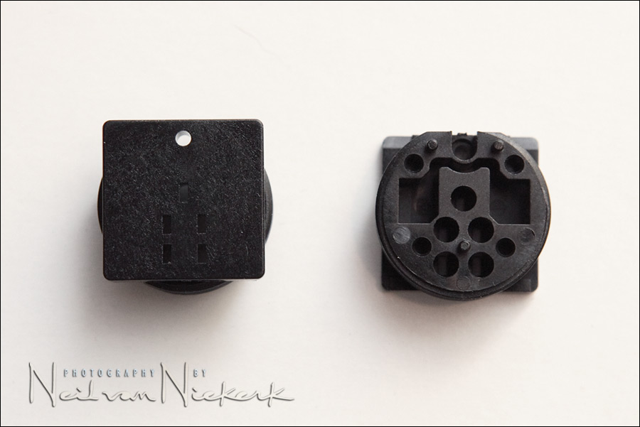
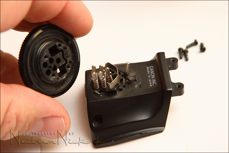
And this is what the spare part looks like – top and bottom views.
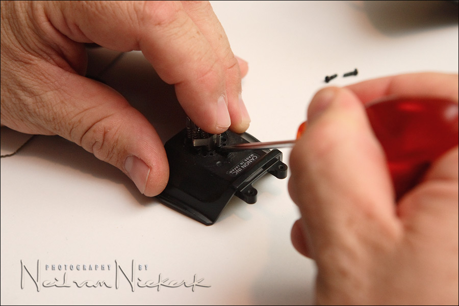
First step is to remove all four screws at the bottom of the speedlight.
Gently wiggle the base section loose.
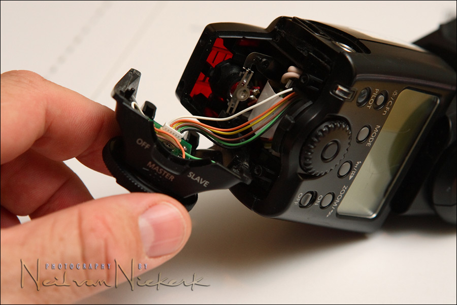
The connector seen in the photo, should be unclipped now so that the base section is separate from the body of the speedlight.
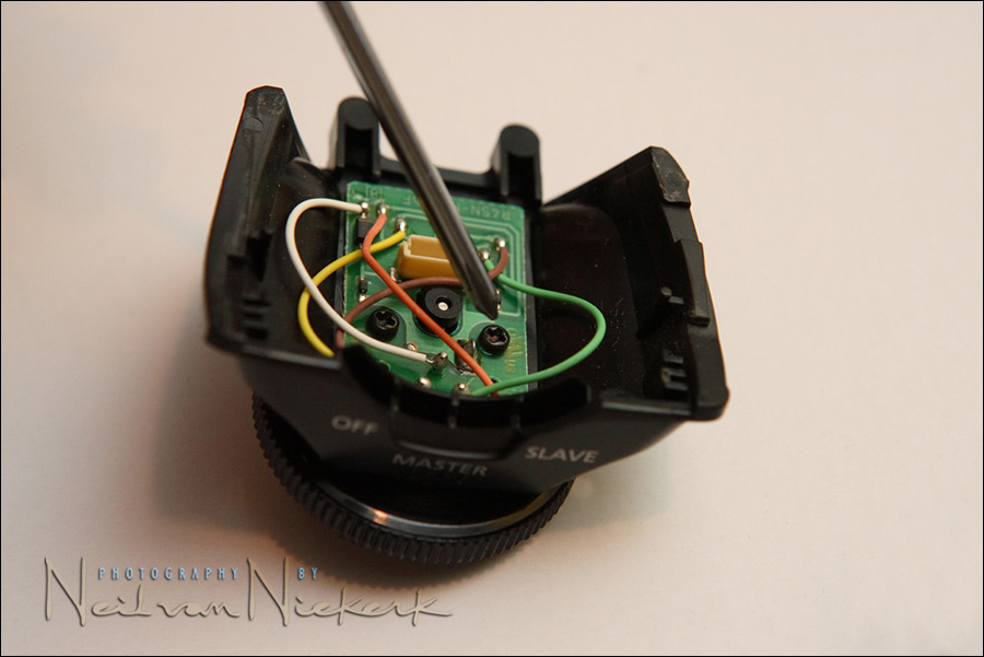
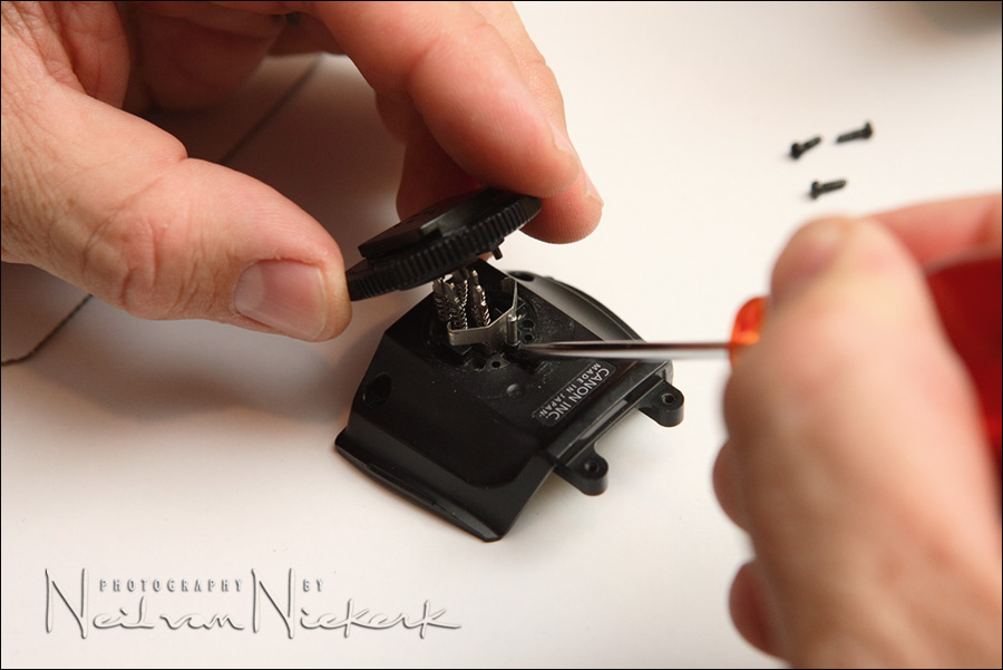
Undo all four screws holding the small printed-circuit board assembly.
But be careful – these 4 screws actually hold the hotshoe foot to the base as well.
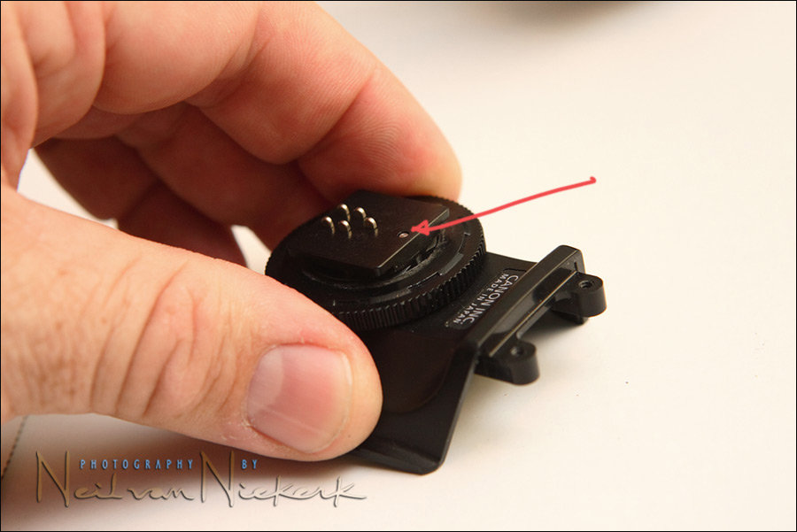
And there is a small pillar with a spring that is just waiting to pop loose on the other side.
Place the base unit upside down, and wiggle the foot loose.
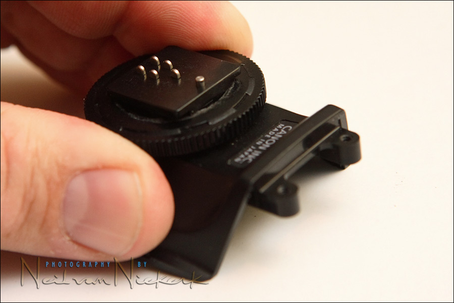
Unscrew the ring from the broken foot, and replace it with the new foot.
Make sure that the new foot is screwed back completely into the ring.
Now the only tricky part is to fit the new foot (with the ring) back onto the base unit – because that spring-tensioned pillar has a tendency to move.
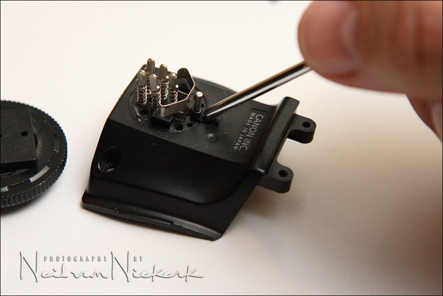
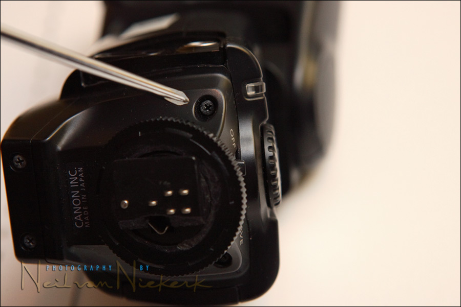
To put the foot back onto the base unit, it is easiest if that spring-tensioned pillar is held into position – a screwdriver tip is good for this.
Clip the foot firmly into position, and screw the foot and printed-circuit board assembly back.
Double check that the movement of that spring-tensioned pillar is correct for when the ring is tightened to either end of its movements.
Now screw the base section back onto the body of the strobe.
There you go. Done!
Mark Peters offered this tip which makes re-assembly easier:
I tried exactly what you illustrated and had difficulty holding the locking pin in place. What worked for me was to put the locking pin in the foot first and hold that piece in my left hand – locking pin with spring on it pointing up. Then I lowered the other component on top of it, making sure all the pins lined up.
Once the pins were properly aligned, I just pushed it together, held it and screwed it back together. Tried the other way about ten times – this method went the second time (first time is when I figured out you had to screw the lock down first.)
A good alternative, while you are busy with a screwdriver on your speedlight, is to replace it with a hotshoe foot from Flash Zebra where they have a mini jack sync port built in. Genius!
Thats fantastic mate, thank you very much.
My 30d with 100-400L and 580ex fell off the dining room table onto carpet today and the flash is the only thing which sustained damage (thank god). The hotshoe looks almost exactly like your picture.
Bookmarked and feeling much better about it now.
I’ll try and find the part and get it repaired with your instructions rather than send it off to a service centre or claim on the house insurance.
What a find, excellent stuff :)
Cheers
Matt
Hi again.
I got the part from http://www.camera-repair.co.uk – cost £17.63.
I had no trouble at all in getting the pins to stay where I Wanted them and got the locking pin in the hole straight off, just needed a little bit of gentle pursuasion to go all the way up through the hole and I was done.
Less than five minutes and I’m back up and running again.
Thank you again for the fab instructions.
Thanks Neil!
I did use Mark Peters’ tip about flipping it over, and it popped right into place. This was an extremely handy tip and I truly appreciate you taking the time to log and photograph each step so well.
You saved me a good hunk of cash. I couldn’t have done this without you.
Thanks again!
Absolutely Brilliant! The swap out took all of 15 minutes with most of the time ensuring I did not drop any of the screws. Your descriptions and instructions are spot on.
Thank You for taking the time to post this information.
Regards
Rick
Sadly, This just happened to me.
For future reference the direct line to the Canon US parts department is :
732-521-7230
The part is $3.50, so I bought two of them just in case.
2nd day shipping is $9. Total was about $18 USD
This also just happened to me and I called the number that John had mentioned and will receive two day after tomorrow. Thanks for the direct line John.
Also wanted to mention that I called a local camera shop that does not sell the spare part but has them in stock and would do it for me if I was willing to pay about 30.00 bucks.
Order two from Canon with second day air and it came out to about half the price.
WOW!!!! Fantastic!! Perfect directions. If I sent the flash out for repair to Canon it would have been 100.00 +
Thanks Again
Although the foot itself is pretty cheap, the whole foot assembly is less than $30, and is only a 5 minute swap (4 screws and 1 connector). The S/H from Canon is usually the same for the foot or the whole assembly!
I usually keep some of each on hand for the repairs and mods that I do for those photogs who don’t want to do it themselves.
Michael
http://www.MichaelBassDesigns.com
any way to fit the 580ex with the metal shoe from the 580ex II? anyone try?
Is it possible to buy the 580 EX-II metal foot and use it on 580EX model?
Thanks
Will this work with the 430ex or is it just for the 580?
Same thing happend to me this afternoon!!
For future reference anyone in the UK needing this replaced please ring:
01782 413611
H Lehmann Ltd based in Stoke-on-trent
Sent it out £7.50 inc
Thanks for the easy to follow step by step repair guide, cheers :)
Hi there Sam and Paul …
The two flashguns appear to have completely different construction for the hot-shoe foot. They won’t be interchangeable.
Went to use my camera this morning, thought it was secure on the tripod – was I wrong. It bounced on the carpet and the 580 ex ended up a few feet away. I was horrified when I saw the hotshoe foot had sheared. Had visions of house insurance and paying excesses or replacing the flash.
Thought I would have a squizz on the net and found your instructions. What a star. I am ordering the part and should be up and running before you can say Jack Robinson. Thank you so much for sharing this valuable knowledge with us all and for saving us some hard earned cash.
Yours – a very relieved and not so poor photographer.
Hi, I have Just phoned the nice man at H Lehmmans to order my hotshoe.
He told me to make sure the flashgun is totally discharged, otherwise, when you introduce a screwdriver to it, it could be a bit nasty! We don’t want burnt fingers – we will have a perfectly useable flash but nothing useable to take the picture with!!!!!!!!!!
Claire x
Does anyone have any idea of the part number or wear to get the same foot for a Metz 58? I called Bogen in the US and they won’t have the part for weeks and then want me to send the flash in. I’ve taken it apart and it looks like a similar process to the 580 described above.
Thanks, ordered the part are replaced the broken part. quick and easy.
This was incredible. Thanks for posting the detailed instructions. I was VERY impressed.
Great find – dropped my 20D with flash and it snapped off very neatly (much to my dismay). Finding this site sure saved me a packet. Waiting for delivery of the parts here in the jungle to get it back in shape. Thanks again for the help
Outstanding!! I have broken two Canon flash’s in my life and this is a life saver. One question though. Is there a way to get a metal foot? I would think this would be stronger in the long run, but for $3.50, I guess I will just buy a few plastic ones for now.
Thanks! It was simple and I had no issues with the spring tensioned pillar. Thanks to you, I knew what to expect when disassembling. I did find that I had to remove the base unit a couple times to tighten the screws on the circuit board. I was afraid to strip the screws or crack the board but ultimately I just cranked ’em down.
Thanks for the great tip,my 430EX is back up and running all for the cost of £7.50,i take it its the same hotshoe for both Flashguns
i used the `Mark Peters`tip,which worked first time, i did the whole job while i was on the phone!!
a local photographic shop said “that will be expensive,and will take weeks”……..mmm
Donald
It is not a good idea to use a metal foot. The flash foot should be the weak point and made a cheap, easily replacable part. Or else, the camera body would be damaged, with a bent hot shoe or worse still, damages to the pentaprism.
Fantastic! Just replaced the broken shoe on my 430EX. Exactly as per the instructions. Saved me a tonne of money – my local camera shop quoted me £100 to fix it!
Cheers!
Thanks to you I’ve saved myself a small fortune. Had the unfortunate experience of seeing my camera and flash hit the marble floor and break in two. A few cheap spares from Canon and its back to its former self. Fully agree with Mark Peters’ tip on re-assembly ended up doing this before I’d read his tip (moral of the story – read the instructions, ALL of them). Sure beats sending away for repair! Thanks again Neil.
wow..I wish I saw this the last 2 times I broke this and sent it in to Canon…I just ordered the part to fix it again…$12 is a lot better than $100!
Replacement part cost from Canon was under $4. In the process of changing the part the spring-tensioned pillar fell onto a carpeted surface and I lost the spring but found it relatively quickly using a magnet. Thanks for the tutorial. It made replacing the part a breeze.
Awesome! Discovering the broken shoe ruined one shoot… but at least I didn’t ruin a flash.
Ordered the part on a Wednesday (with a spare), got them today (Friday)… used the Mark Peters tip and got the pins aligned in one try.
Life savers!!!!
Note: I have the 430EX, the shoe is the same part (CY2-1227-000) as the one mentioned in the article for the 580EX.
Great! your post saved my life. ;-)
I found the part via ebay – sold by http://www.uscamera.com Paid 19 usd including shipping to Europe.
Took me 5-10 min to change – even without looking at your description. My 580ex is like new again!!!
Thanks for your post!
Thanks!
Just picked up 2 of the new shoes from Canon here in Toronto for $5.75 each!
I followed the instructions and thought my pin was too tight, did not notice that screwing the lock in and out will retract the pin, so I thought my tension was too tight.
Other then that it was flawless.
Thanks again!
WOW, I was dumb and thought I could super glue the pieces back on. Wrong. That did not work. So I got online and found this!
One huge problem though, after the makeshift super glue try I accidentally glued the metal pins themselves to the plastic. That took forever to get off. I think I sawed at the thing for an hour.
Afterwards all was well.
Lesson: Don’t super glue your speedlites folks!
What a beautiful thing.
It is always a spirit booster when you can accomplish something with a little help from your friends :-)
Thank you
Neil. I dont know who you are but this worked like a charm. Had a tiny struggle getting the ring to turn and lock properly, but otherwise your advise and all the follow up with canon’s number etc was phenomenal.
Thanks loads
Thanks for this. ordered 2 hotshoes aswell. took about 4 days to get here and about 15 min to install. couldn’t find a small screw driver for like an hour of searching but finally got it!
Great instuctions. I have a 430ex, so beware, there is no circuit board inside this model, just the four screws very close to the circuit lines (be careful not to break them lose).
I actually have long nails and when I started I was worried because I was not sure if my nails were going to be on the way to handle the small pieces. Surprisingly my nails were the ones that help me hold the pin down and it was so easy… Thanks!
Living in Ireland, tripped over a
photographing a wedding at the weekend and broke the foot of a second 580EX. So pleased to find your helpful site and clear instructions. Have ordered four new parts (two spare!) from Lehman Camera Repair in UK and am hopeful of fixing both flash guns…thank you again
Well, I just used your instructions for the second time! Thankfully, on the first occasion I had ordered three of the parts so I had two remaining. I must admit, the second time I broke my flash I was more sanguine about it than the first!
Thanks again!
I ordered the foot on ebay. With standard shipping it came to about $13. I referred several times to the instructional images posted here and they were the key to successfully replacing the foot. The foot I received was slightly defective; one of the three plastic alignment pins was bent and would not enter into its hole. That created a tiny gap that kept the five electrical connectors from passing fully through the foot. Only their tips came through. I did not know that was the reason at the time. But I knew something was not right because it did not look like the picture. So I took it apart again, took a close look and noticed the bent pin. I filed it down with an emery board, just enough for it to fit into its hole. That worked. The connectors aligned perfectly, and I screwed the assembly tight.
Many thanks for a well written and well illustrated article.
My tripod-mounted camera, lens and 580EX flash hit the floor a couple of days ago after I stumbled on a rabbit hole.
Camera and lens was fine but 580EX’s shoe snapped. I expected a £100 repair bill which would have made it an expensive day out.
Thought I’d have a quick browse on the web to get an accurate indication of repair. Came across this article straight away, phoned the telephone number given above for Lehmanns. Spoke to a particularly friendly and helpful chap who told me exactly what part I needed and gave me a few tips for fitting it. Ordered it there and then on Thursday afternoon, 8.00am the following day it arrived. Price was £11.75 (inclusive of v.a.t. and postage).
Excellent, profesional, helpful and fast service from Lehmanns.
Just fitted it two minutes ago. The whole procedure took under ten minutes, if that. The spring-mounted pillar went in instantly and first time. The only tricky thing about the whole operation was remembering where my screwdriver was ;)
Many thanks for sharing a great article.
Great article,
Saved me a US$118.00 service charge from Canon USA!!
hmmmm….i wish id found this earlier.i did the same as chris and tried to superglue the thing together and am now having a nightmare trying to get the damn thing off!!everything was going smoothly up untill that point.Dont superglue your speedlites folks!!!!!!!!!!!!!!!!
Neil,
It was so gracious of you to put so much time and effort into this excellent illustration and I want you to know that it was truly helpful. It was also helpful reading some of the replies with info on where to purchase parts.
Thank you and God bless you all,
Mike
Was out this evening and lo and behold – camera fell off the table and shoe came off flash. Luckily the camera was off – USM L lens is fine as is body however flash hotshoe has gone the way of the dodo. This website has saved my life! :)
This post turned a sad evening into a much better one. My camera was sitting on the seat of my wifes car with the flash on my 40D. My daughter ran to the car to get in from the rain and sat down right on the camera. My flash looks exactly like yours. Thanks for this detail repair info. I will order my part today and start surgury right away. Scaple….
You star. I thought that was going to be expensive but this great guide did the trick. Only took a few mins.
Mark Peters tip about the pin made it easier and thanks to another comment on here I remembered to take out the batteries and discharge the flash before starting work.
Cheers for taking the time out to put this up. This is why the internet’s great.
All fixed ! 13 minutes from disection to test fire. I might add that the stofen difuser makes a great little screw caddy for those little screws.
Thanks again for this post!
Andy G.
after a very small fall on the ground from about 20 cm the shoe of the flash broke — i was shocked how easy this flash breakes. I hope i can get it repaired at reasonable cost since this really is no good for the image of canon, that flash basically is a piece of plastic but with some vulnerabel high tech parts inside. no good combination.
Thank you so much for the repair help! The hot shoe broke on Tuesday. I typed it in in Google and found this fabulous tutorial. I jumped on the horn with Canon and got replacements today (Friday). You just saved me some dough and from having to use a cheep flash at event I had to do today. Thanks again.
I don’t suppose you would know of the equivalent part numbers for a 580ex II ? My little boy dropped my camera with attached flash and the hot shoe has snapped clean off, and the pin is now bent.
Check out this thread on the 580EX II broken hotshoe .. someone posted a link to the part.
Thanks Neil.
I feel the need for a broken-flashgun support group.
Hopefully I’ll be able to pick up the oem part in Oz without too much difficulty
Great job… saved 100 + euro’s thanks to you….
€ 1,72 part, 10 minutes work. I wished IKEA had manuals like this.
Many, many thanks
24-70L,420EX,20D fell from 2 ft. looked exactly like the diagram. took me under 5 minutes total. (Microwaved shrimp-rice-salmon-asparagus while doing it) Wow stomach and wallet are smiling! Thanks Oh the repair shop hit me for 15 bucks but on the package they have cost at $2.45. Still happy
Hi, this illustration is wonderful, but I’ve got a 430EX. Where can I find a similar procedure to replace the 430EX shoe? Thank you
Thanks for the tutorial, you make it look easy and I’ve just replaced a broken foot on my 580EX.
Good job !!!
I have a Metz 48 AF-1 and the plastic foot has broken. It was originally for a Pentax mount, but if possible it’d be great to replace with a Canon mount. Does anyone know if this is doable? And if so what the product ID is?
I damaged a 420EX, and it was easily repaired following your instructions above!
Very kind of you to compile this info and I am very thankful!
Nice tutorial. I was able to install a new foot easily, however the lock collar ring is catching on the new foot. It appears that the ring was damaged along with the original foot. Do you know if I can order a new ring as well? They should really sell the two items together. Thanks.
Was wondering…. In process of replacing part of hot shoe…. broke saddle connection…. tried to supperglue , but does not seem to sinc with camera or work. Any hope?
WOW! Thanks. Fixed my 580EX. Was afraid it might be lost when it broke when my 7D fell… fortunately no 7D damage and the 580EX damage was repaired with help from this page.
I am trying this with my 580ex & it seems to work smoothly, but when I reattach flash to camera it seems slightly loose.
I had a heck of a time getting the circuit board screws out, I think the heads of them may be stripped & not tightening the board down enough.
Does anyone have an idea what I may be doing wrong?
Thanks Neil for the original post.
Thanks Robert,
I am sure it is the replaced part on the bottom of the flash it is not
seated properly & I can see plastic threads a bit by the tightening lock (not sure if this is normal)the camera body is brand new & a 550ex flash is tight when locked down.
Hi, just recently my wife had the shoe foot break on her flash. she has a Canon Rebel XTI and uses a Digital Concepts flash 736AF/CAN. My problem is that I have not been able to track down a replacement part. We live in Edmonton AB and all the camera shops her tell me I will have to leave it with them and they will send it in for servicing (avg of $50-100 to repair). There is no way I’m paying that when I’ve seen how cheap and eay it is to repair this.
Does anyone know where I can get a replacement foot? Will the 580EX hotshoe fit?
Any help will be greatly appreciated. Thanks
Thank You Very Much for this blog. I almost paid over $110.00 to get it replaced. it took me less than 5 minutes to fix it my self. Funny thing is now my 580EX II stopped working.
Thank you Neil and Mark!!! I performed this procedure successfully (using Mark’s tip). I ordered directly from Canon – very smooth and quick. The part was $3.50 and $6 shipping. I ordered two, so for $14 I fixed my flash and I have a spare foot for my next “incident” :)
THANK YOU!!! I about died when my 4 yr olds dropped my camera and flash onto the floor and I saw the flash was broken. I was so nervous about telling my husband I needed a new flash….until I found your instructions! I just finished replacing the foot and it was so simple. Thank you again!
Thank you very much. Good detailed instruction on how to replace the CY2-1227 shoe. I thought I have to buy a new 580EX.
Will having a broken foot not cause the flash to fire when it’s mounted to the camera?
The description here of the broken foot is most often (if not exclusively) that of the plastic flanges breaking off. Not an electrical short inside. So a broken foot won’t case the flash to fire .. you simply won’t be able to mount the flash to the camera.
Thanks a million – a ten dollar part, ten minutes, two screwdrivers and a little patience is all it takes. My backup 580ex is flashing again and ready for action.
Chris
Ditto with Chris above! Got the part on e-bay in 3 days, and with this pages instructions, I have wiped away my tears! ;) Thank you times 100!
Thank you SO MUCH!! I followed exactly your instructions and my flash is working again, thanks for sharing! Wieneke.
Thank you for the information (Canon US parts department is : (732-521-7230)
Ordered part 12/15/2010. Part is $9.50. I wanted to update this since July 2010 post said $3.50. With ground shipping, which take 5 business days total was $9.90.
i just did all this but when i finally put the new shoe on the camera, the ring got stuck and i couldnt unlock it.
i just spent a few hours trying to maneuver the screws out of the flash while it was on the camera (had to resort to using an Xacto blade to get the screws out at the awkward angles) to disassemble the body again and finally managed to loosen the ring with some pliers, since i was too afraid of breaking it off again while the whole flash body was still attached
any thoughts as to why this might have happened/how to prevent it? i’m not going to try to reassemble the flash until i am sure this wont happen again.
not sure what’s worse: broken foot or foot stuck in hot shoe!
Could the ring have been cross threaded on the post? It’s pretty loose on my 580 EX until tightened against the camera shoe.
You are a life saver! I followed the instructions exactly as they are and replaced my broken shoe. The flash is working again! Thanks a million!
Ya, the 430 ex part is not sold seperate but for $25 plus $6 shipping theyll send the whole hotshoe assembly repair… just ordered it.
I normally don’t comment on blogs, but as this is the second time in two years that I referred to this article to repair my 580, I felt that its time to say thank you to Neil.
Great stuff! and I thankfully ordered TWO hot shoes when it broke the first time, so when I fell to the floor on Purim, and heard the flash fly off the camera and skoot along the floor I didnt even blink. I knew I had the parts and can look this up once again for the details as to where the damn spring has to go!!
Hello!
Thanks for this, I just contact our Canon service in Slovenia and their price for this part and replacement is 92USD. I ordered one piece from USA via Ebay, for 14USD with shipping and taxes. :D
Hi, thanks for posting this info. I used it last year to fix my 580ex, and now I need to fix my 430ex. Before I get started, someone said fixing it is a little different and I wondering if anyone had any tips before I order the part and get started. Thanks.
It worked. I have a big conference to shoot today and my husband changed my broken hotshoe on a 430ex flash unit last night and it worked beautifully. Thanks so much.
The part only cost $10.00
worked like a charm. remember to put the skinny side of the post down and the fat side up, and the spring goes on the skinny part. jiggle the shoe until the pins go in. it’s tricky, but it works!
Thanks Neil!
BTW, a friend of mine attended one of your workshops, was wondering if you ever do workshops in DC ?
-Rick
Thanks Neil. Your instructions were very helpful. I repaired my broken foot just now.
Will
Thanks Neil! Your instructions worked like a charm. I had my 40D attached to 430EX fall down with a broken shoe foot. I ordered the part at https://uscamera.com/product/canon-speedlite-420ex-430ex-flash-shoe-foot-cy2-1227/ and was able to fix it with my 7 year old Son in 15 minutes.
-Sourabh
Ordered the hot shoe foot from San Diego Camera Solution, shipped to Michigan, cost was $10.50. Worked like a charm. Took 15 minutes to install to my 580EX. Directions were great. Thank you!
Thanks Neil, The tips are spot on and I was able to repair my 550ex speedlite, Big relief to my pocket too. Cheers.
Thanks for the great instructions. My 580ex foot broke a few months ago when it fell 6 feet from my truck to asphalt, so I’ve been using my backup 550ex intending to send the 580ex to Canon for repairs. Then the unthinkable happened Tuesday when I tripped and broke the foot off my backup! And I had a big shoot scheduled for Saturday.
I started Googling Wednesday morning and found this site. I ordered two feet from San Diego Camera Solutions ($10.50 each) plus $20 for overnight shipping. They got here today and I’ve now got two good flashes again. Thank you!
Incidentally, for those reading this who need to repair a 550ex, the foot is the same as the 580’s, but the wiring, etc. to get to it is completely different. Still, I read over these directions for replacing the foot on the 580ex and was able to fix the 550ex too. In fact, I did it first to “practice.” Whew! It’s a tough one! But once I got it done, repairing the 580ex was a piece of cake.
Another big thank you. I called Canon Canada and when I asked for the parts department the call center said the only number they have is for Global Semi at 1 (800) 668-8776 or you can order online at http://www.globalsemi.com. It looked like a hassel to set up an account online so I just called in now and was on hold for about 5 to 7 min
Part CY2-1227 was approx $6.50 + $15 for Express Post delviery to Calgary. Total cost is $22.49 with tax. They said if I was local I could pick it up at 5600 Timberlea Blvd. Mississauga, Ontario
Estimated shipping time was 3-5 days as they had to order the part in first.
Hope this helps some of the Canadians out there
Thanks Neil, your instructions are perfect and it gave my 580X a new lease on life.
The part itself was $3.50 from Canon U.S.A, shipping was $7.
You can call Canon Parts Center at: 1-866-481-2569
Part#: CY2-1227-000
hey – good tutorial. I referenced it on another forum.
Something I wanted to address – it is easy to forget which way the master/slave switch goes in. I added some pictures of the assembly order.
Hopefully someone will find this useful!
http://heavymod.com/battle-canon-550ex-flash-hot-shoe/
love your site – been learning all about lighting from your articles.
Very old post, but I need help!
A small rubber ring fell out of somewhere while I was doing this repair, and how the spring pin isn’t springing back once pushed down. Not sure if this problem is related, but please help!
Thank you so much for this. I had the EXACT same broken part on my hotshoe when it fell out of my camera backpack. I was able to buy the part for $15 from US Camera (…. well $30, I lost it the first time since it’s so small) and avoid the $100+ repair at canon!
This page was EXACTLY what I needed. I fell, skinned my knee, but more importantly, broke the same part of the 580EX hotshoe as pictured here. I also ordered the part for $9.26 (on special?) from US Camera (plus $14.25 International Shipping, plus currency conversion to Canadian). I found that with conversions their price still beat Amazon.ca and ebay.ca.
Thank you!
Thank you! save me some trouble. The spare part was not available in the UK canon due to age, so had to find it on ebay.
Greetings, this is a fabulous site of much help, I want to know if any of the friends have or can refer me somewhere to obtain the service diagram of the Sigma EM-140 DG flash, I want to fix it myself, very grateful.